Rebuilding a Rega R200
This arm is nice. I like it.
The R200 was commissioned by Rega to go on the original Planar turntable, built by Acos, and is a derivative of the original equipment arm that was on the Rega's first deck, the Planet.
Rega bought in the arm for the planet, it had a simplified version of the Acos Lustre GST-1 on it. The R200 is a derivative of that simplified Acos/Rega arm.
Sans the sliding base and height adjustment, the Acos/Rega itsself was identical to the one separately available from Acos as a standalone arm.
Acos were a japanese OEM manufacturer, the same as Jelco are, their products or derivatives of were fitted to most japanese turntables of the day.
It was more economical to contract out that part of the design process, leaving the manufacturer of the turntable free to devote the time to the deck itsself. Their arms are very nicely built.
The R200 was used until Rega decided to produce their own arms, the ubiquitous RB series.
Wether the RB series were any better than the previous gen arms is questionable. To me at least, having listened to them both in succession, and taken both to bits and studied them.
This particular R200 was obtained to complete a deal enabling me to get my grubby hands on a Mayware Formula 4 unipivot to partner my JBE series 3 and Audio technica AT150 SA.
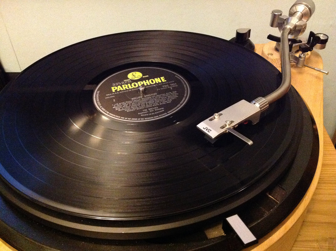
The deal was with a customer of mine, who bought the first lenco conversion I built, to get a medium to high mass arm to partner a goldring e3. I was to obtain said medium to high mass arm, rewire and rebuild it, and fit it to the Lenco. I would then get the Mayware for my deck. So far, so good. An Acos lustre GST-1 was looked at but wouldn't fit as the base was too big for the lenco plinth. The R200 was eventually settled upon. Here it is as I received it, dropped onto the deck it would eventually call home. You will note that the hole in the deck does not match the arm. More on that later
The R200 was commissioned by Rega to go on the original Planar turntable, built by Acos, and is a derivative of the original equipment arm that was on the Rega's first deck, the Planet.
Rega bought in the arm for the planet, it had a simplified version of the Acos Lustre GST-1 on it. The R200 is a derivative of that simplified Acos/Rega arm.
Sans the sliding base and height adjustment, the Acos/Rega itsself was identical to the one separately available from Acos as a standalone arm.
Acos were a japanese OEM manufacturer, the same as Jelco are, their products or derivatives of were fitted to most japanese turntables of the day.
It was more economical to contract out that part of the design process, leaving the manufacturer of the turntable free to devote the time to the deck itsself. Their arms are very nicely built.
The R200 was used until Rega decided to produce their own arms, the ubiquitous RB series.
Wether the RB series were any better than the previous gen arms is questionable. To me at least, having listened to them both in succession, and taken both to bits and studied them.
This particular R200 was obtained to complete a deal enabling me to get my grubby hands on a Mayware Formula 4 unipivot to partner my JBE series 3 and Audio technica AT150 SA.
The deal was with a customer of mine, who bought the first lenco conversion I built, to get a medium to high mass arm to partner a goldring e3. I was to obtain said medium to high mass arm, rewire and rebuild it, and fit it to the Lenco. I would then get the Mayware for my deck. So far, so good. An Acos lustre GST-1 was looked at but wouldn't fit as the base was too big for the lenco plinth. The R200 was eventually settled upon. Here it is as I received it, dropped onto the deck it would eventually call home. You will note that the hole in the deck does not match the arm. More on that later
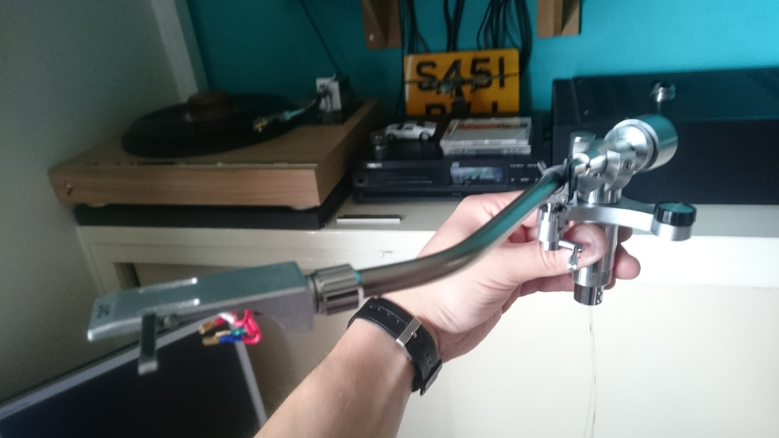
The headshell is not the original one, its a Pioneer, but thats ok, it looks the part and is close enough to the original.
Cosmetically the arm was perfect, not a mark on it. Mechanically, it wasn't. The socket in the base of the arm pillar was missing and the wiring cut off. The usual problem of a perished bias belt was evident by the untethered rotation of the bias dial. But as the arm was going to be rewired anyway, the missing socket and damaged wiring was largely irrelevant.
Would have been nice if the socket was there though.......
First, lets crack on with the bias belt replacement.
If you read t'internet, this is apparently a complete pig of a job that needs 3 hands and a degree in something or other to do it. Well it doesn't. What it needs is a quiet environment, a set of basic tools, and patience.
Firstly, you need a belt. They are no longer available, so you may need to scour the web for a suitable replacement. I got one from ebay from a very knowledgable chap who also provided a set of comprehensive instructions on fitting it. the belt was longer than the original, but the chap who sold the kit has had a small half moon shaped tensioner piece laser cut from acrylic to provide the correct tension. It is a very well thought out kit, so thanks need to be given to him for it.
In order to fit the new one you need to be able to get at the old one. Or the remains of it. This will be alot easier if you remove the arm wand first by taking the vertical bearing pins out. Once the wand is removed, secure the yoke in a vice so its upside down. It's easier to get the retaining nuts off the bottom of the bearing shaft if you do this as it stops the yoke turning. Use your common sense and put something relatively soft either side of the yoke so the jaws of the vice don't make a mess of it. To get at the belt you need to remove the bottom lateral bearing from the arm which is retained with a pair of locking nuts in the base of the arm post. First, there is a screw in collar with 2 set screws in it that needs removing. A set of mole grips will get this off if like this one, it's done up too tightly to remove by hand. Then take out the 2 retaining nuts. Do this carefully as these 2 nuts are what preloads the ball race underneath them.
Remove them and you will see a floating ball race which you need to remove with tweezers and under this the actual bearing cage. Again remove with tweezers. DO NOT force any of these parts, finesse is your friend.
When you have done this, remove the 2 retaining screws underneath the bias outrigger to remove the outer of the arm post and the cover which is a one piece casting.
You will then be able to remove the remains of the belt and fit the new one and its tensioner. You will need to reset the bias to 0 first. Set the dial to 0, then turn the collar that moves the movable ring magnet. Set it so that this magnet is positioned as far away from the fixed magnet as possible.
Then fit the belt, pull it away from the bias outrigger casting wall, and fit the tensioner piece in so it sticks to the inside wall of the the casting.
Refit the outrigger cover/ arm post, and stop. Go make a cup of tea. Then come back to it. This is where the patience comes in. First, drop the bearing cage in. Look at it before you do this and you will see that one side is different to the other. One side has the face of each ball proud of the metal cage, and the other doesn't. It needs to be put in so that the ball faces are facing out, as the race needs to run on them. When you drop the bearing cage in make sure to seat it properly by poking it into the machined recess with a cocktail stick. Then drop the bottom race in. The groove in it rides on the balls in the bearing cage so this needs to be dropped over the yoke shaft and wiggled into position so it seats properly on top of the bearing cage.
Then screw the retaining nuts in. Just do them up lightly as they set the bearing preload. Don't worry if there is wobble in the lateral bearing at this point.
Then refit the arm wand. Having rewired it already. Obviously. unless you want to take it to bits and rebuild it twice. It needs to be back on for the preload to be set correctly. You will feel lateral and a little vertical movement at this point.
Turn the bottom nuts until the movement is gone. You can see when it is right as setting the bias to 0.5 should start to slowly move the arm back to the rest when the preload is correct. So when you can't feel any movement, and the bias starts to very gently pull the arm back at 0.5g, you've got it.
I then added a blob of nail varnish to stop any movement in the retaining nuts.
Job done. Partly.
Rewiring the arm wand is simple. Remove the wand from the arm by removing the vertical bearing pins and sliding the wand forward so it clears the sides of the yoke, then remove the retaining set screws for the headshell connector. Before you do anything, you will need to measure the gap between the yoke and the wand. measure it with a steel ruler flat against the top of the yoke, lined up with the front edge, and butt it up to part of the wand that protrudes above the flat top of the yoke. and write the measurement down. The reason will become clear later. Using the curved end of a 6" steel ruler inserted into the end of the connector will allow you to crack it off so it comes out. When it's off, thread the wiring through the tube and insert a headshell into the removed connector. The reason for this is to push the pins out to make it easier to solder the wiring to them, and to keep the connector still while you solder. Makes this bit much easier. I used Transfi litz for the job as it is very flexible and sounds really good.
Turns out that was a bad idea on this occasion, as after a couple of hours use, the edge of the machined hole where the wiring comes out of the wand cut into the silk sheathing on the wire and shorted it. Had to rewire it twice, which was a complete pain in the arse as it meant starting from scratch. I rewired it with Cardas silver the second time. Still like the Transfi litz better........
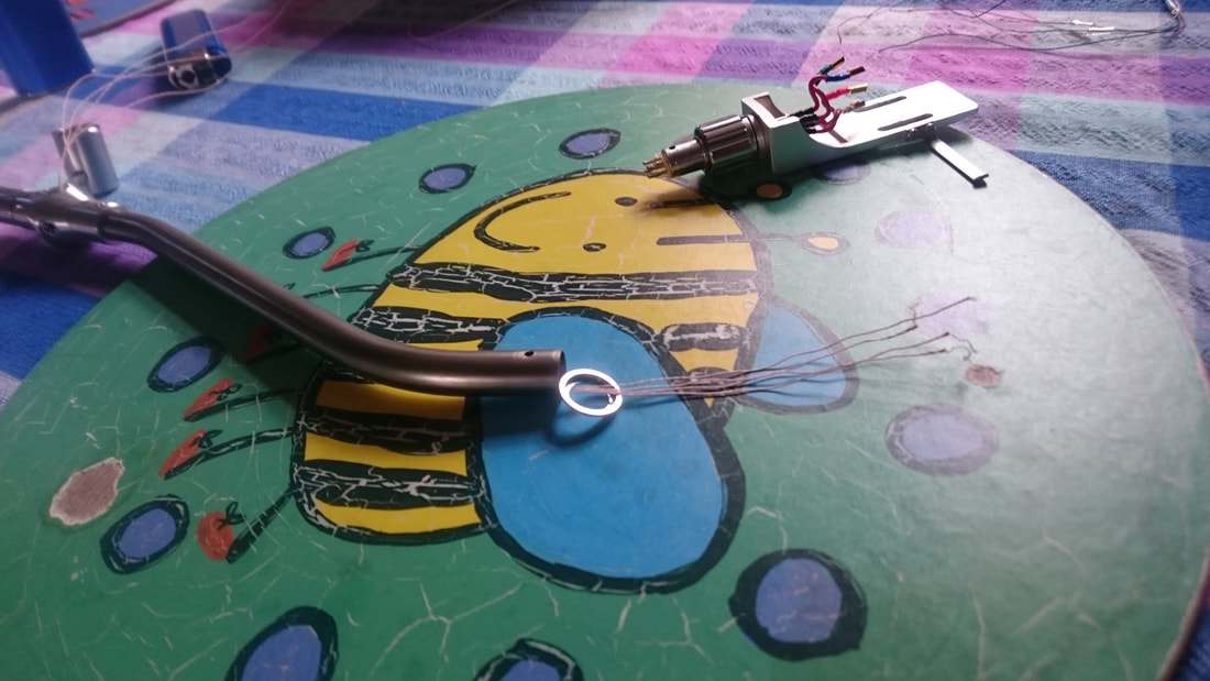
Make sure when you wire the new wiring to the connector pins, that you retain and refit the clear plastic sheathing that goes on the pins as there is bugger all clearance between them. A teeny little whisker of wire could short the signal to ground, resulting in bugger all output.. remember to tin the ends of the wiring, it will be a right pain in the arse if you don't. You should end up with something like this................
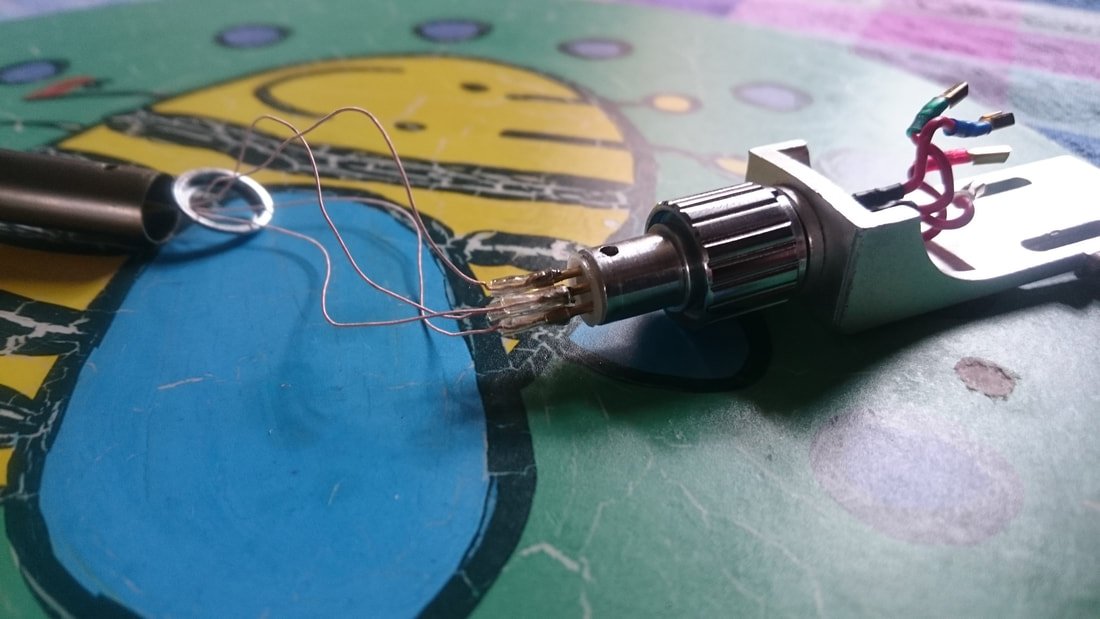
Shove the connector back in and secure it with the setscrew, then thread the wiring down the arm pillar in the centre of the yoke, INCLUDING the arm wand earth and the arm pillar earth. Refit the bearing pins, and you should have something like this, with a good 2 1/2 feet of wire hanging out. Note the chromed steel collar sticking out of the base of the arm, this will come in rather handy later. This is the time to set the bottom lateral bearing preload as described above, and reset the vertical bearing pin preload at the same time. You will know when the vertical bearing pin preload is right, when the wand moves freely with no rocking motion. The ticklish bit is getting the wand centred. The measurement of the gap between the yoke and the wand that you did earlier (you did do this didn't you?) will come in very handy for this. (told you it would become clear). Then, with infinite patience, nip up the locknuts so the pins stay where they are. Remember, patience. Zen and the art of patience if like me, you don't have all that much hair left and available for pulling out. It can be a complete arse to nip up the locknuts without moving the pins, but persevere.......
So. Now we have a rebuilt, rewired, and reset arm with a load of wires hanging out of it.
We now need a usable outer loom. The next step was to find a way of retaining a sleeve for the wires, a braid for screening, and an outer braid for covering it up. So abit of lateral thinking later, and some measuring with the calipers and we have a solution.
The collar that screws into the base of the arm has an ID of 12mm, and I have a length of 1/2" ramin dowel hanging around. So I cut a 3/4" length and drilled 2 holes in it. I would have preferred to use delrin, but I didn't have the required diameter, only 10mm. One hole was drilled down the centre to take some 4mm PTFE sleeve that the signal wiring will run through, and an offset 2mm one for the earth wires to run through. The sleeving was glued into the hole in the dowel with some hot melt glue. The wiring was threaded through the sleeve with about 4" left hanging out of the other end, and the earth wires for the wand and pillar were threaded through the other hole. A braid stripped out of some coax was put over the sleeve and soldered to the earth wires. If you strip the braid as I did rather than buying some in, make sure the braid is steel as if it is aluminium you wont be able to solder the earth wiring to it. The braid was then also hot melt glued to the 1/2" dowel. This was then put up into the threaded collar and secured in place with the setscrews. So we now had the beginnings of a screened cable.
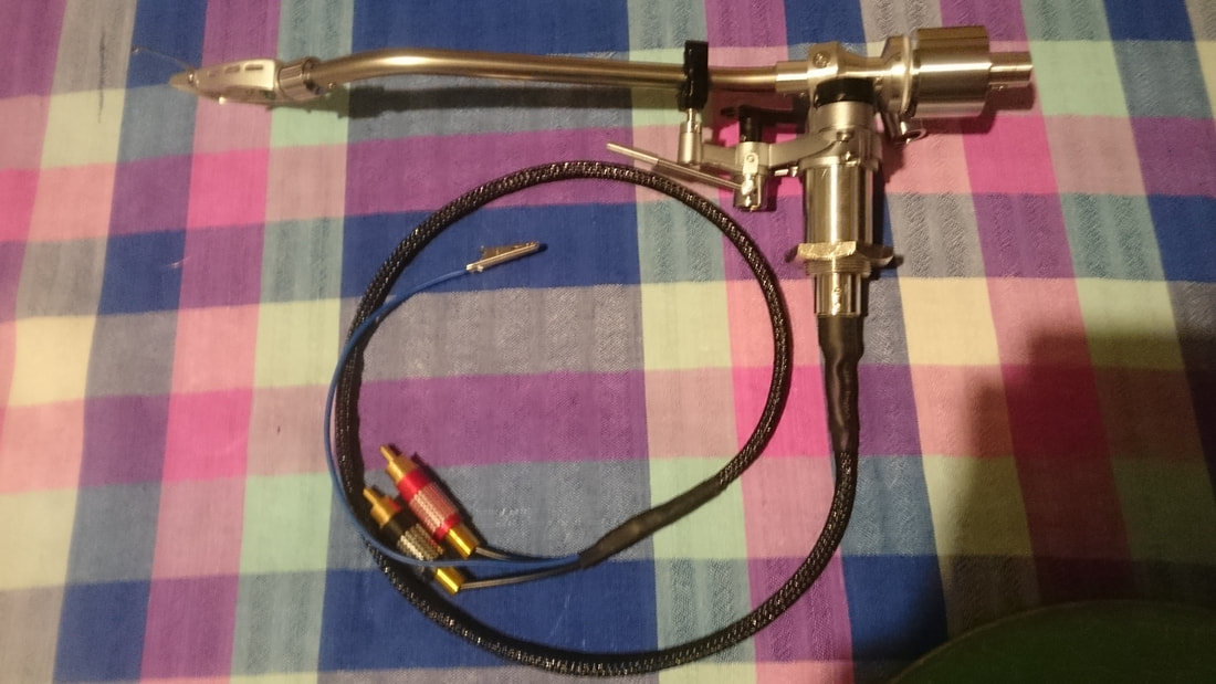
The next thing was to sleeve over the braid with some plastic outer braid that was bought online for the loom. The hot melt glue at the dowel end was heated back up with a lighter and the outer braid pressed into it to retain it, (yes I did burn myself.......) and then heatshrink was shrunk over the lot. Now nice and secure, it won't come apart without heat or being cut.
At the other end, a wire with a crocodile clip was soldered to the other end of the braid. This will clip to the phono stage, and mean that the wiring is shielded from end to end once clipped to a suitable earth. At the plug end, lengths of sleeving were put over the 2 wires for left and the 2 wires for right, separated by putting a meter on the headshell leads and bare wire ends, checking for continuity to identify each one as nothing is colour coded inside the loom. Some black electrical tape over the lot to secure it all at the plug end, and then some more heatshrink over everything completed that part. Solder on the plugs, and hey presto, a completely rebuilt, rewired, reset and rejuvenated Rega R200. Apart from the fact that I had to rewire the arm tube with the Cardas wiring and rethread it down the completed outer loom which was time consuming and aggravating, that was pretty much it. The other thing to do was to turn a new base for the arm to fit the deck.
We now need a usable outer loom. The next step was to find a way of retaining a sleeve for the wires, a braid for screening, and an outer braid for covering it up. So abit of lateral thinking later, and some measuring with the calipers and we have a solution.
The collar that screws into the base of the arm has an ID of 12mm, and I have a length of 1/2" ramin dowel hanging around. So I cut a 3/4" length and drilled 2 holes in it. I would have preferred to use delrin, but I didn't have the required diameter, only 10mm. One hole was drilled down the centre to take some 4mm PTFE sleeve that the signal wiring will run through, and an offset 2mm one for the earth wires to run through. The sleeving was glued into the hole in the dowel with some hot melt glue. The wiring was threaded through the sleeve with about 4" left hanging out of the other end, and the earth wires for the wand and pillar were threaded through the other hole. A braid stripped out of some coax was put over the sleeve and soldered to the earth wires. If you strip the braid as I did rather than buying some in, make sure the braid is steel as if it is aluminium you wont be able to solder the earth wiring to it. The braid was then also hot melt glued to the 1/2" dowel. This was then put up into the threaded collar and secured in place with the setscrews. So we now had the beginnings of a screened cable.
The next thing was to sleeve over the braid with some plastic outer braid that was bought online for the loom. The hot melt glue at the dowel end was heated back up with a lighter and the outer braid pressed into it to retain it, (yes I did burn myself.......) and then heatshrink was shrunk over the lot. Now nice and secure, it won't come apart without heat or being cut.
At the other end, a wire with a crocodile clip was soldered to the other end of the braid. This will clip to the phono stage, and mean that the wiring is shielded from end to end once clipped to a suitable earth. At the plug end, lengths of sleeving were put over the 2 wires for left and the 2 wires for right, separated by putting a meter on the headshell leads and bare wire ends, checking for continuity to identify each one as nothing is colour coded inside the loom. Some black electrical tape over the lot to secure it all at the plug end, and then some more heatshrink over everything completed that part. Solder on the plugs, and hey presto, a completely rebuilt, rewired, reset and rejuvenated Rega R200. Apart from the fact that I had to rewire the arm tube with the Cardas wiring and rethread it down the completed outer loom which was time consuming and aggravating, that was pretty much it. The other thing to do was to turn a new base for the arm to fit the deck.
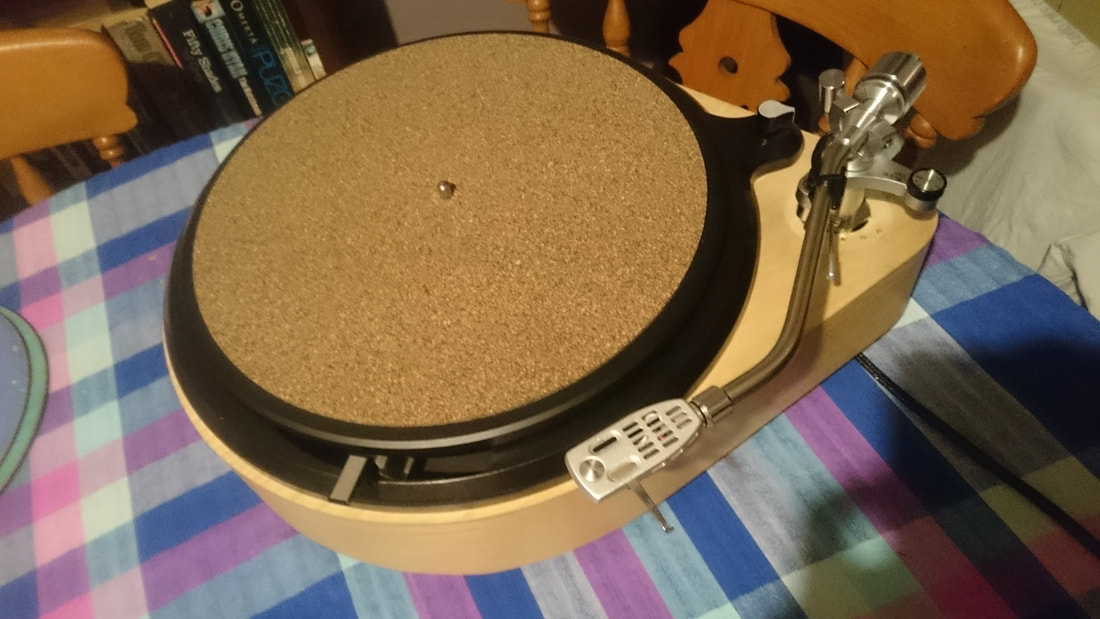
As the deck it was to go on was originally built for a Rega RB251, the arm hole in the plinth was already in the right place as they both have the same mounting geometry. The next step was to turn a new mounting for the arm out of a block of solid oak. It ended up looking like an inverted top hat, the thinner part a resistance fit into the plinth, the wider flange part set the arm height with its thickness. This has to be altered with shims if needs be. The front of this was then cut off with a bandsaw so that the bottom of the raise/lower device cleared it. this was then sanded and finished, completing the job.
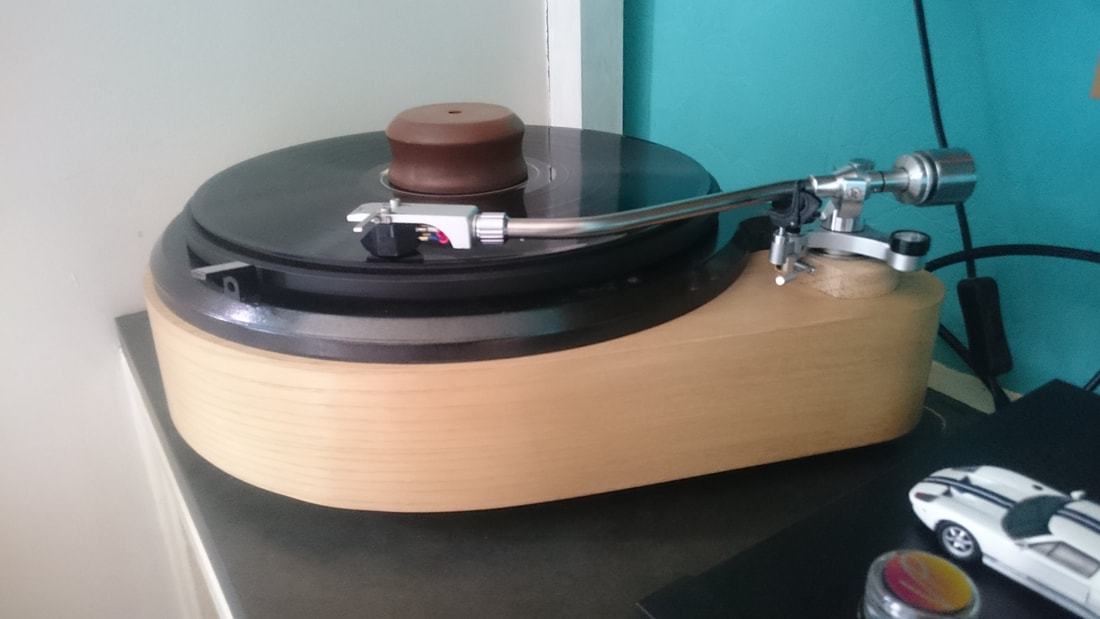
It was then sent off to its owner to enjoy, who sent me the picture below of it playing. Incidentally, the pioneer headshell turned out to be too thin to fit the Goldring E3 into, the cart is that wide that it fouled the little mounting screw for the fingerlift. So my JVC headshell had to go with it until a replacement was found. Its a really nice sounding cartridge though, a bargain for a ton.
Its a very nice sounding arm, very musical, very silky. The fit and finish is superb, rivalling anything produced in the uk at the time, and other than SME, probably bettering it. The camera chromed arm tube and satin aluminium finish is lovely, and the quality of the machined parts is as good as anything produced these days. Cracking value for money, I wouldn't hesitate to put a nice headshell and a moving coil cartridge in it. Frankly, I like it better than the RB series, and the fit and finish is much better than one of those. A completely different league. Acos knew what they were doing when Rega commissioned them to make these.
A little gem, with a simple rewire making it worthy of a much more credit than it gets. And it looks lovely to boot