JBE series 3 slate turntable restoration
I really like my JBE series 3 turntable. It contains elements that I find essential in a good turntable. It has a very 'dead' plinth system, an unflappable drive system that is speed stable (hence pitch stable) and a very neutral character.
I think it was way ahead of its time in terms of the materials used in the late seventies, and it is a crying shame that the company went under and these stopped being produced.
However, the HiFi press at the time were dead set against direct drive in general, other decks such as the amazing trio LO-7D, and other japanese super high end decks were pooh poohed at the time, and some incredible products never made it to these shores at all. Nothing could compare with the lp12 in their eyes at the time. The Flat Earth movement effectively put paid to JBE which is a damn shame.
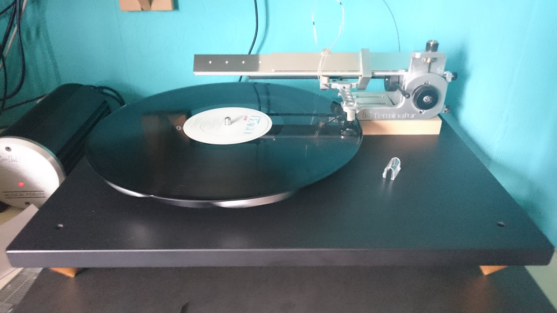
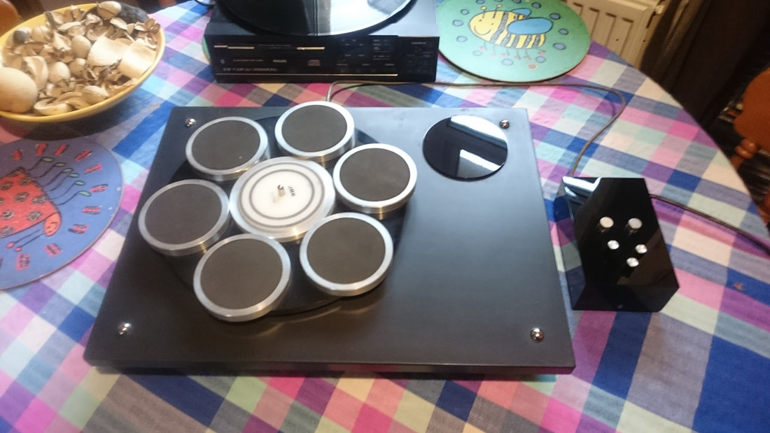
This is my own modified (fixed, sic) version of the JBE circa 2012 ish, sporting a modified Rega RB251 and a MK1 Ortofon MC10
I think it was way ahead of its time in terms of the materials used in the late seventies, and it is a crying shame that the company went under and these stopped being produced.
However, the HiFi press at the time were dead set against direct drive in general, other decks such as the amazing trio LO-7D, and other japanese super high end decks were pooh poohed at the time, and some incredible products never made it to these shores at all. Nothing could compare with the lp12 in their eyes at the time. The Flat Earth movement effectively put paid to JBE which is a damn shame.
This is my own modified (fixed, sic) version of the JBE circa 2012 ish, sporting a modified Rega RB251 and a MK1 Ortofon MC10
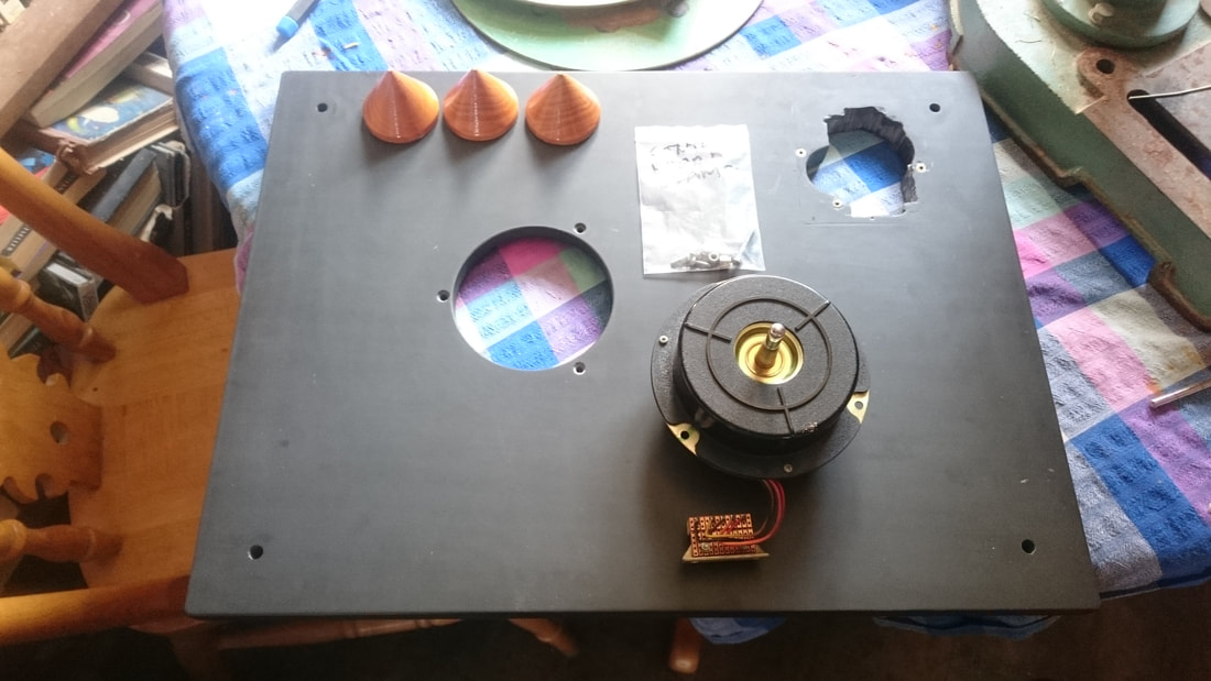
My version uses 3 turned applewood cones instead of the original Micro Seiki Microsorber legs it came with.
The original legs had perished rubber and when the deck was being handled by a courier and was DROPPED! (yes it was, don't lie to me....) all the plastic parts of them were shattered. However, due to the perished rubber I had already been looking at changing them for solid ones. Personally, I am on the fence when it comes to isolation techniques for turntables, being a subscriber to the idea of getting the energy out of a plinth.
To me, rubber feet, isolation feet of any description work two ways. They stop extraneous energy getting into the deck, but they also stop it getting out.
any deck will have an inherent amount of energy bouncing round its insides when it is being used. Firstly the energy from the motor and secondly the resonances from the arm and cartridge.
The motor noise needs to be dealt with by either getting it out of the system, or isolating the rest of the system from it, e.g decouple the motor from the bearing, platter and arm in some way. But then you end up with a belt drive, and I consider that a flawed solution in terms of pitch stability and control of the platter. I prefer to get rid of it, to sink it out through solid legs.
The energy from the cartridge also needs to be able to get out. As the stylus vibrates as it follows the groove, the movement transfers energy into the cart body, which then dumps this energy into the arm. Which is why I prefer a rigid arm mount rather than decoupling. I'd rather it wasn't bouncing around in the arm tube, a rigid mounting will sink it out into the plinth and then out of the system into the support.
Slate will naturally absorb much of this energy and what it doesn't, now has a path out into the slate support, and built in unit it is stood on, and out into the surrounding structure. I personally find this approach cleans the sound up no end and reduces colouration. I really like a clean sound which is what the JBE gives me.
Wanting to do a better job of rebuilding the deck rather than the half hearted job i did to get it running again after its run in with Mr Myopic courier, I started a complete strip and rebuild of the motor as it had not been touched since the build date in 1979!
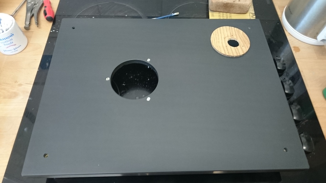
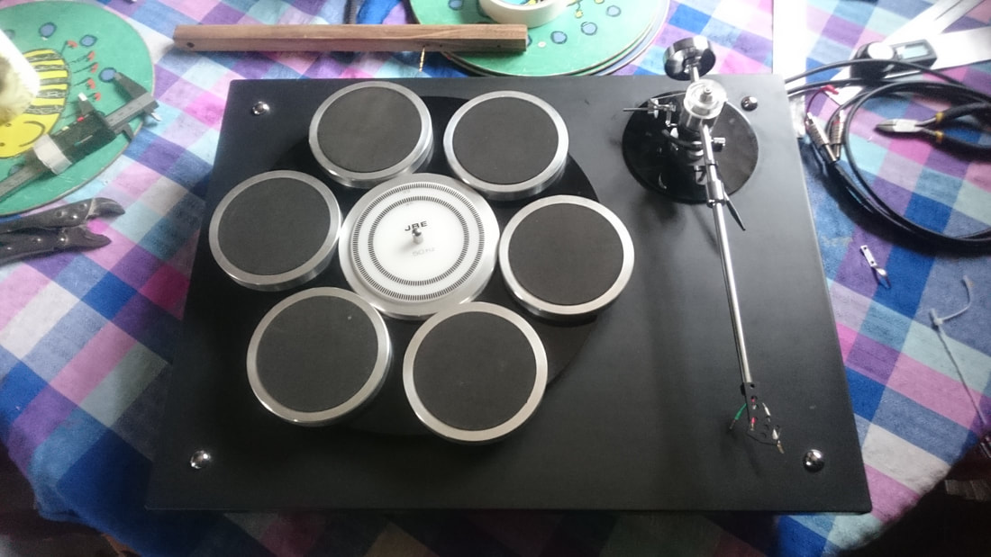
Here is the slate plinth sans arm and motor. It looks very grey as I had sanded the slate back with water and 2000 grit sandpaper to clean up some surface scratching
The original legs had perished rubber and when the deck was being handled by a courier and was DROPPED! (yes it was, don't lie to me....) all the plastic parts of them were shattered. However, due to the perished rubber I had already been looking at changing them for solid ones. Personally, I am on the fence when it comes to isolation techniques for turntables, being a subscriber to the idea of getting the energy out of a plinth.
To me, rubber feet, isolation feet of any description work two ways. They stop extraneous energy getting into the deck, but they also stop it getting out.
any deck will have an inherent amount of energy bouncing round its insides when it is being used. Firstly the energy from the motor and secondly the resonances from the arm and cartridge.
The motor noise needs to be dealt with by either getting it out of the system, or isolating the rest of the system from it, e.g decouple the motor from the bearing, platter and arm in some way. But then you end up with a belt drive, and I consider that a flawed solution in terms of pitch stability and control of the platter. I prefer to get rid of it, to sink it out through solid legs.
The energy from the cartridge also needs to be able to get out. As the stylus vibrates as it follows the groove, the movement transfers energy into the cart body, which then dumps this energy into the arm. Which is why I prefer a rigid arm mount rather than decoupling. I'd rather it wasn't bouncing around in the arm tube, a rigid mounting will sink it out into the plinth and then out of the system into the support.
Slate will naturally absorb much of this energy and what it doesn't, now has a path out into the slate support, and built in unit it is stood on, and out into the surrounding structure. I personally find this approach cleans the sound up no end and reduces colouration. I really like a clean sound which is what the JBE gives me.
Wanting to do a better job of rebuilding the deck rather than the half hearted job i did to get it running again after its run in with Mr Myopic courier, I started a complete strip and rebuild of the motor as it had not been touched since the build date in 1979!
Here is the slate plinth sans arm and motor. It looks very grey as I had sanded the slate back with water and 2000 grit sandpaper to clean up some surface scratching
and with the motor cracked open to have a good poke around inside and asses for wear. The motor is a Matsushita MKL 15 B3, there are lots of derivatives of the MKL motor in lots of Japanese direct drives, such as the Trio/Kenwood KD500/550.
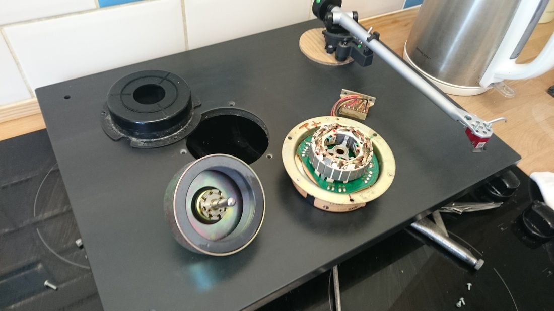
A very nice piece of kit. There was no wear evident on the bearing shaft or the phosphor bronze bush, I couldn't see or feel any at all. Which was quite surprising as there was very little bearing oil left.
As oil is hygroscopic, and what lubrication remained was nearly 40 years old, the remaining lubrication was a milky puddle of gloop in the base of the bearing. The thrust pad had a small dent in it as you would expect after so long, but it proved impossible to work out how to get it out without desoldering the motor control board from the motor coil assembly.
So I cleaned it all up and left it in situ.
With new bearing oil in it and a good clean, it spins up alot faster and seems alot smoother. The rotor can take a while to settle back into position when reassembling, this is normal and is due to the tight manufacturing tolerances.
A nice simple service to a very good quality motor, any JBE owner can do this.
Re oiling the plinth was the last job after screwing it back together and for now it now had it's lovely sheen and mojo back :-)
Leap forward a couple of months, and having built the Lenco demonstrator, the JBE was mothballed for a while. I intended to do a complete restoration of the deck, rather than the half arsed job I did when I got it back from its run in with the courier. The original work was done simply to get it up and running again, and while fit for purpose, it could have been done better. It will never be standard again, but that doesn't mean it cant be done to a high standard.
Things that I need to address are the terrible hole in the plinth, the finish to the slate which is still poor, the rather nasty motor block connector which is dodgy at the best of times, and the PSU case which has a large crack in the top surface.
Before that though, I did have some fun with a borrowed Transfi Terminator air bearing arm......
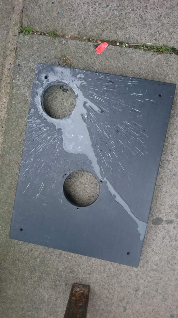
Finding some time and enthusiasm to make a start, I bought a diamond holesaw for cutting a 'proper' hole in the slate to address the first issue. I'm not sure what on earth the previous owner had cut it with, or why, but it had been done so badly it could have been done with a bread knife for all I know. So it was stripped down again
I needed to use water while cutting the slate for 2 reasons. Firstly to provide cooling for the diamond holesaw, and secondly to stop the very nasty dust from being thrown everywhere. I still wore the appropriate mask even with the water.
In order to cut a hole which has sides square to the top surface, I used a drill stand. In this, I used my 110v drill and site transformer, and strung the cables up high to make sure there was no way the cooling water would get near anything.
In order to keep the water where I wanted it, i.e around the cut itself, I used an old pop bottle with a small hole drilled in the cap. That way it had to be squeezed in order for the water to come out, and the stream was small and direct-able.
I first needed a guide for the holesaw as there is no central guide bit. I put the holesaw in a pillar drill and used it to drill a hole in a piece of ply that was then clamped into position above the original hole, and guided the holesaw when it was used in the drill stand.
I then drilled into the slate to a depth of about 2mm without water to provide a key, removed the guide, and then went all the way through while squirting the water into the cut. Went through like a hot knife through butter and left me with this
And once cleaned up, with the motor, platter and legs reinstalled, and abit of sanding and oiling of the plinth, I had this. Which looks like it could almost be standard.
I had kept the original fixings for the Micro Seiki feet, so these may be used for a new set of legs.
I had kept the original fixings for the Micro Seiki feet, so these may be used for a new set of legs.
Plan is to turn some new legs for it on my lathe, and turn a new arm board with a 5mm flange to fit the new hole. The board will then be removable so that new boards can be made for different arms. I have yet to decide what wood to use.
The next thing to address was the PSU casework. This has been twatted quite badly as a result of the mishandling by the courier. The 45rpm speed adjust control was hit pretty hard which had punched it through the top surface causing the cracking.. So I cracked it open to get some measurements for the panels.
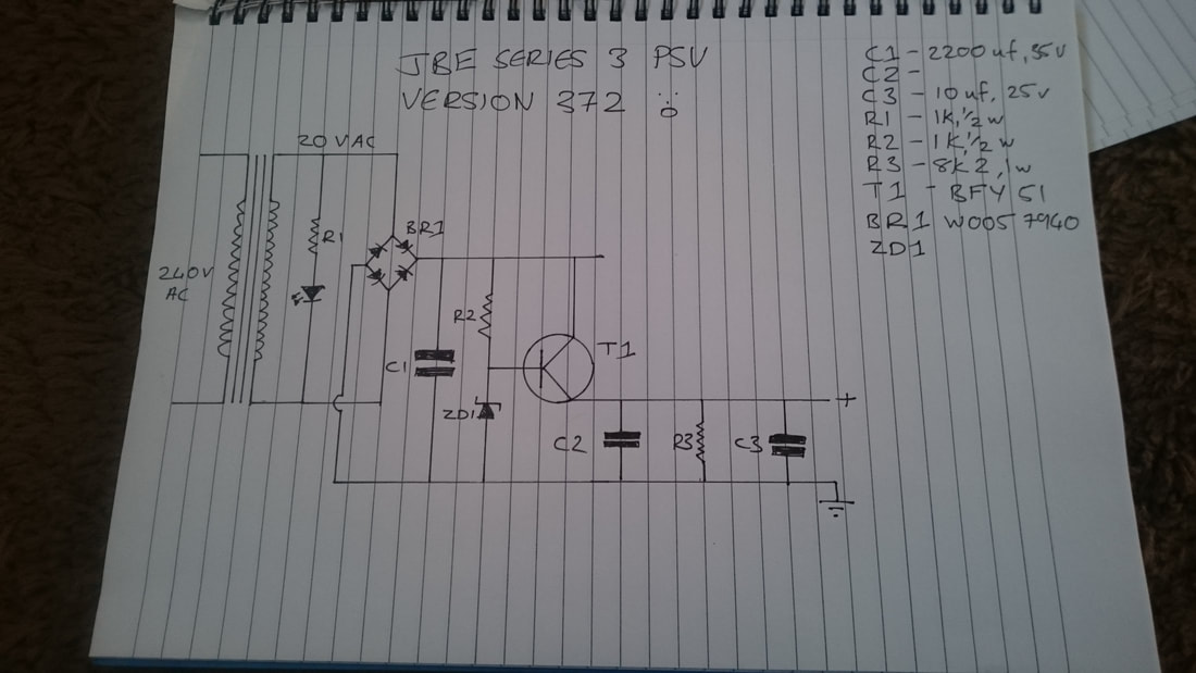
And while I was at it I decided to trace the PSU circuit as I have been unable to find a schematic of this online.
The next thing to address was the PSU casework. This has been twatted quite badly as a result of the mishandling by the courier. The 45rpm speed adjust control was hit pretty hard which had punched it through the top surface causing the cracking.. So I cracked it open to get some measurements for the panels.
And while I was at it I decided to trace the PSU circuit as I have been unable to find a schematic of this online.
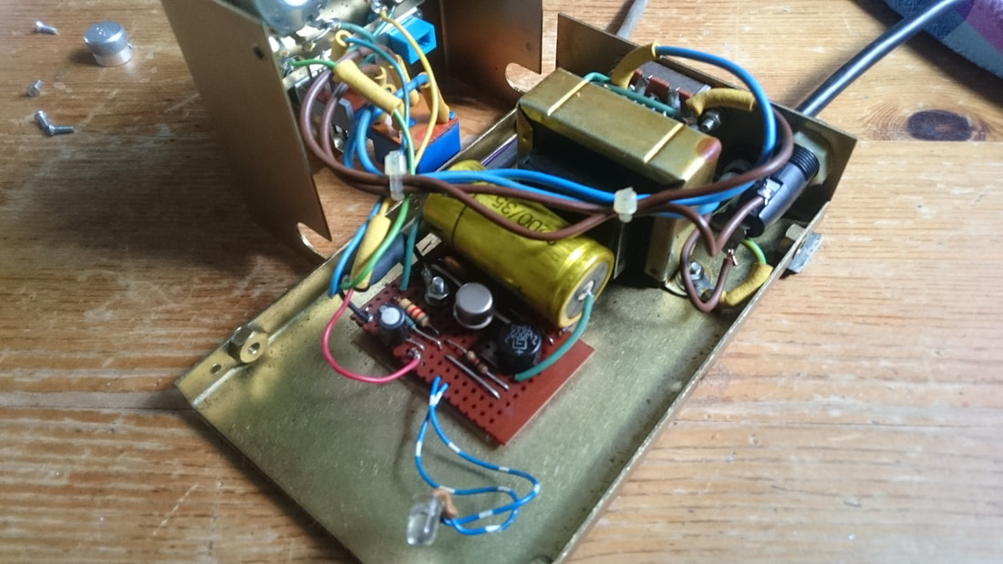
My PSU is made on stripboard, and was abit of a pig to trace due to some decidedly bad soldering and the lack of a tab on the transistor that is used as a current amplifier. I couldn't tell from the can which way around it was. The 3 pins on it are arranged in a triangle so it looks the same whichever way around it is.....
In the end, I asked for help on a forum I frequent and was able to get the correct orientation for the transistor based on the surrounding circuitry, and ended up taking the transistor off the board to make sure. The pins were marked up on the underside...... unfortunately I couldn't tell what the value of c2 was, or the type of zener diode used (zd1) so thanks need to be given to Nick Gorham for pointing me in the right direction with the circuit
In the end, I asked for help on a forum I frequent and was able to get the correct orientation for the transistor based on the surrounding circuitry, and ended up taking the transistor off the board to make sure. The pins were marked up on the underside...... unfortunately I couldn't tell what the value of c2 was, or the type of zener diode used (zd1) so thanks need to be given to Nick Gorham for pointing me in the right direction with the circuit
I also took some measurements of the PSU once I'd put it back together. Mine outputs 20.1vdc with no load and 19.6vdc under load with the deck spinning. This seems a little high, I was expecting nominally 18vdc. I was also able to measure a small ac voltage under load that was around 0.3vac so there is measurable ripple.
The supply voltage also fluctuates by around 0.5v. This could be partly due to its age.
I have got a line on a small regulated power supply board that could possibly be used in place of the original board as a replacement but i'd need to try it to be sure. If it could be used as a drop in replacement that would be rather useful.
To be continued.....................
Fast forward a week waiting for parts to arrive, and the next step was to give the deck 4 legs again, the PSU casework on hold for the moment. Now trying to find a replacement set of the Micro Seiki Microsorber damping feet it originally had, is like trying to find a feathered frog. There are some out there, (microsorbers that is, not feathered frogs......) the Japanese seem to have plenty, but the cost of importing some is prohibitively expensive. Infact, trying to find another series 3 is proving difficult at the moment. I do keep my eye out for them, regularly checking the usual places, but its been quite a while since I saw one.
So I made some.
When I changed to solid legs instead of the shock absorbing legs I noticed an improvement in several areas. Firstly, the imaging sharpened up somewhat and the sound became a little cleaner, abit more focused. As I mentioned earlier,I think the mechanism behind this is that the vibration that is bouncing around in the slate from the motor and the arm has a way out. The slate does a very good job of controlling this resonance as it is, but coupled into something else via the cones, the remainder that it can't control is dealt with too.
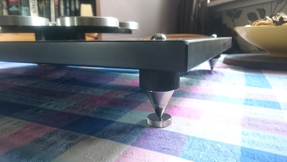
There are 6 parts to these legs. The cone itself is nickel plated brass and is in 2 parts. The spike part at the base is threaded into the second section to give levelling adjustment.
The 'shoe' it sits in is the same nickel plated brass, and stops it scratching the support platform. The black part is a piece of walnut I turned on the lathe and then sprayed matt black. I painted it to make the legs fit in with the deck visually, to keep the continuity of colours and finish. But to also add in a different resonant characteristic. Wood has different damping properties to the slate and the brass, helping with the damping of resonances in the plinth. The fifth and sixth parts are the mounting screw and cap. I used these screws as I wanted to have a close to stock look, i.e for the caps to be as close to the original aluminium fixings for the feet.
I can be too pedantic sometimes when it comes to the way things look, but being a pedant has its benefits sometimes as I think the legs work well visually.
The total height with the shoe under the spike is 48mm which should give enough clearance when using an arm that has a plug in cable with a straight DIN plug.
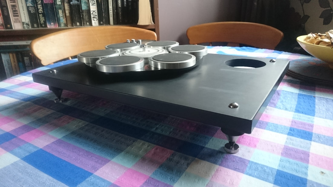
I want it to look like something the factory could have built eventually, a series 4 perhaps, if they had continued developing the deck and had not faded away.
Onwards!
Fast forward a couple of weeks, and I found time in between jobs to complete some more work on the deck.
The first thing needed was some way to mount a tonearm. Obviously. Without one, its a nice ornament but less than useful.
So. I wanted to keep the arm mounting board in keeping with the rest of the deck, so I went for an arm board with a black acrylic 'deck' and a piece of turned walnut as the locating piece that would drop into the new hole. The black acrylic face is larger than the hole in the plinth ands forms a flange once the turned walnut drop in is glued on.
Then there was the issue of locating the board in the hole and keeping it there. As the hole position has been dictated by the dogs dinner of an arm cutout, the mounting hole for the arm will likely be offset from the centre of the board. So a clamping system had to be devised so that once the arm mounting hole is in the correct position, it would stay there. The solution was to have a pair of clamping blocks underneath so the board grabs the underside of the slate .
These clamping blocks were faced with rubber so they could be screwed down hard and the rubber faces would ensure the board can't move. Worked perfectly, leaving me with no visible fixings, and this.
While iI was at it, I polished up the psu case. Anticipating scratching the black perspex on the arm board face, I had bought some proper acrylic polish. The stuff is called Quixx, and is bloody good. The psu case still has the cracks in it, but is at least nice and shiny again. It was a step too far to recase it at this point. Maybe in the future.
The next thing to consider was an arm. Obviously. Still a nice ornament at this stage.....
Then I got lucky. The customer of mine who bought the first Lenco conversion I built had decided to change the arm on the deck I'd built him, and wanted me to alter the deck to suit.
The deck had a Mayware Formula 4 on it, and a deal was struck. He wanted a higher mass arm as he had changed his cartridge from an Audio Technica AT440 MLB to one of the new Goldring E3 cartridges, the change due to a run in with an errant cat for the former...........
The brief was, that he wanted something medium to high mass, something seventies, and something built like a brick outhouse. An Acos Lustre GST1 was mooted, but the base for the arm would not fit on the deck. Enter a Rega R200. Built by Acos as an OEM arm for Rega before they decided to make their own arms, in most respects it is very similar. And would fit on the lenco with no problems. Needless to say, I bit his hand off.
The struck deal was that I would acquire an R200 and rebuild it, then fit it to the Lenco in exchange for the mayware. Great I thought, Everyone's happy, Im quite capable of rewiring and fitting a new arm to it. Turns out it wasn't so easy, but more on that later..............
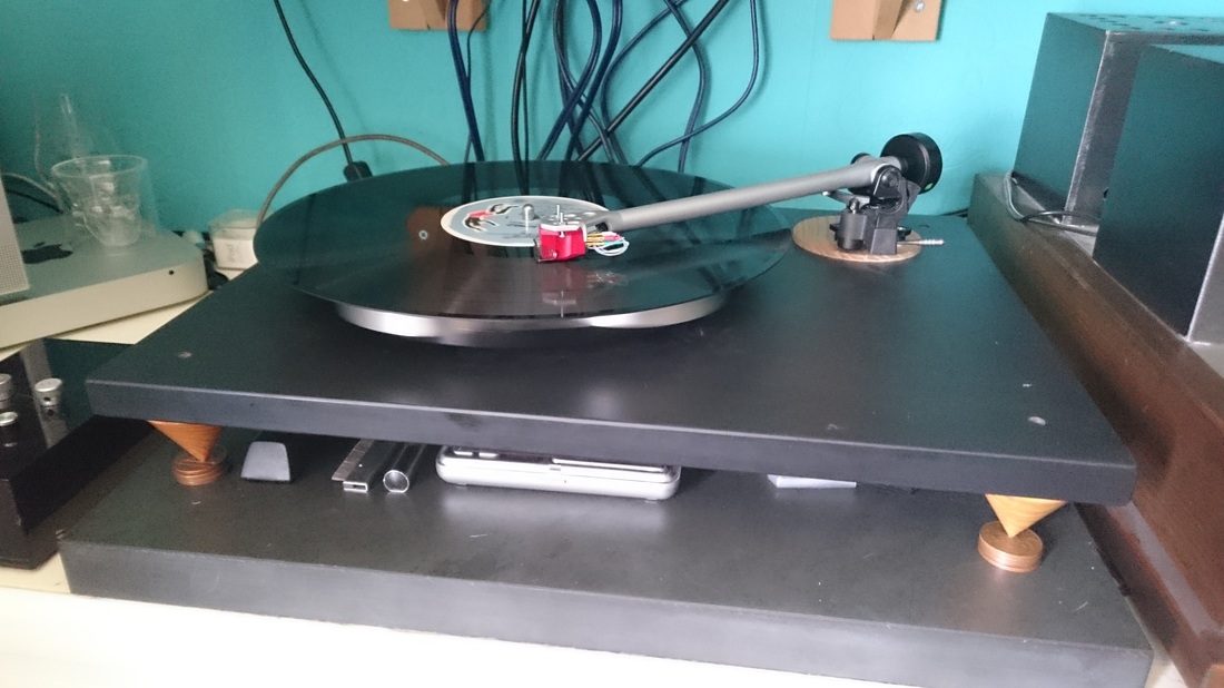
The Formula 4 was a period arm for the JBE, lots of dealers used to fit the arm to it in place of the SME 3009. Usually with a Sonus blue or Shure V15. I know a couple of people who were dealers at the time and they agreed that the combination was a very good one.
And it certainly is
The next thing to consider was an arm. Obviously. Still a nice ornament at this stage.....
Then I got lucky. The customer of mine who bought the first Lenco conversion I built had decided to change the arm on the deck I'd built him, and wanted me to alter the deck to suit.
The deck had a Mayware Formula 4 on it, and a deal was struck. He wanted a higher mass arm as he had changed his cartridge from an Audio Technica AT440 MLB to one of the new Goldring E3 cartridges, the change due to a run in with an errant cat for the former...........
The brief was, that he wanted something medium to high mass, something seventies, and something built like a brick outhouse. An Acos Lustre GST1 was mooted, but the base for the arm would not fit on the deck. Enter a Rega R200. Built by Acos as an OEM arm for Rega before they decided to make their own arms, in most respects it is very similar. And would fit on the lenco with no problems. Needless to say, I bit his hand off.
The struck deal was that I would acquire an R200 and rebuild it, then fit it to the Lenco in exchange for the mayware. Great I thought, Everyone's happy, Im quite capable of rewiring and fitting a new arm to it. Turns out it wasn't so easy, but more on that later..............
The Formula 4 was a period arm for the JBE, lots of dealers used to fit the arm to it in place of the SME 3009. Usually with a Sonus blue or Shure V15. I know a couple of people who were dealers at the time and they agreed that the combination was a very good one.
And it certainly is
The next issue once the arm was fitted was not to do with the deck. It was to do with she who must be obeyed.
I was told in no uncertain terms that I was not to remove the JVC QL-Y5F and replace it with the JBE, as she "was not going to use that thing". Reason being, that she has gotten used to being able to play records with the JVC and its push-button-to-play robot arm with no fear of busting a 400 quid cartridge , and flatly refuses to use the JBE as it "has a wobbly arm and I cant cue it".
Ever since she broke a nude Denon DL-103 with fritz gyger stylus about 10 years ago (t'was not cheap......) by miscuing it, she seems to have a pathological aversion to manual turntables.
Which is fair enough I suppose.
So much much faffing later, including building shelves into the built in cupboard that the system sits on for the Pass F5 amp to sit on, and much whittling about the fact that an amp that gets pretty hot is now in an enclosed space, (hint: the F5 doesn't care that its in a cupboard. I went to the length of borrowing a laser thermometer from a friend who uses one as part of his job to see if it was getting overly hot. Is doesn't, but I still can't help checking, must be my ocd.....) I got the deck installed in the system........
His and Hers. Or something.............
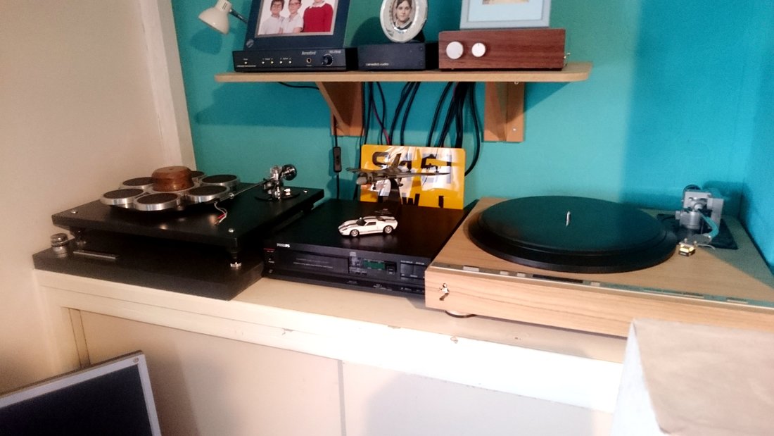
You may also note, that the cd player is not a Philips CD160, I acquired another, a Philips CD371 which has a CDM2 transport rather than a CDM2/10. But thats a story for another page.
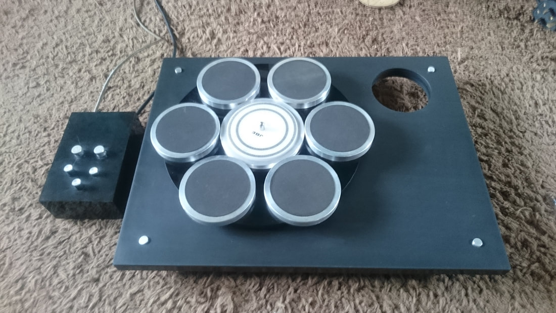
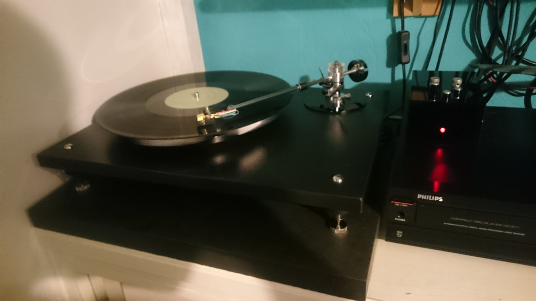
I swapped the Audio Technica AT150 SA over from the JVC to the JBE, and fitted the JVC with my Goldring Eroica L. Having managed to break my AT-F7. (and she is the one worrying about buggering up cartridges...........) Reasoning that as the AT is much higher compliance than the Eroica, it would be better to put it in the Mayware. It works very very well indeed with the JBE and the Mayware, and the Goldring is more than happy in the robot arm. Result! Also, a note to other JBE users, don't bother with a record weight unless you put a shim under the strobe disc in the centre of the platter, its lower than the top of the pads on the pods so it tends to dish the record. I turned mine myself from a block of very old oak and it weighs 200g, so reasonably light, but ain't much good unless there are shims in place under the strobe disc.
I swapped the Audio Technica AT150 SA over from the JVC to the JBE, and fitted the JVC with my Goldring Eroica L. Having managed to break my AT-F7. (and she is the one worrying about buggering up cartridges...........) Reasoning that as the AT is much higher compliance than the Eroica, it would be better to put it in the Mayware. It works very very well indeed with the JBE and the Mayware, and the Goldring is more than happy in the robot arm. Result! Also, a note to other JBE users, don't bother with a record weight unless you put a shim under the strobe disc in the centre of the platter, its lower than the top of the pads on the pods so it tends to dish the record. I turned mine myself from a block of very old oak and it weighs 200g, so reasonably light, but ain't much good unless there are shims in place under the strobe disc.
So. It's finished and sounding better than ever. It still has a wonderfully balanced sound, rock solid pitch, and a beautifully clean quality. The Mayware and AT 150 are a brilliant partnership. Much better than the Rega/Ortofon combo. Comparing to the JVC, it is a little tighter, a little more detailed, a little cleaner. It builds on the strengths of the JVC, although the JVC is a little warmer in character. Ive thought about this, and I think it's down to the plinths. Its very hard to say which one I prefer. It depends on what mood I'm in. If I want to sit there and relax and get lost in abit of Art Pepper, I'll use the JVC. If I want to jump about like some sort of idiot to Deep Purple, I'll choose the JBE. Or vice versa. I love them both. As the Americans might say, 'I sure admire your problem'
Going forward, there are some bits I would like to attend to. I might try some different legs, I may re case the psu, and I'd like to replace the sorbothane pads on the top of the platter pods with some new rubber. If I can find a die the right size to punch some new discs out.
But for now, I think I'll just enjoy it
Fast forward to 2021................
I haven't updated in a while, but I've done some bits and pieces lately.
I got abit bored today and was tidying through a load of my many boxes bits and pieces. I was chucking bits and pieces that have been in one of the boxes for god knows how long. I found a small 5 pin locking connector, which set wheels turning, so I decided to replace the awful old connector on the JBE that connects the control box to the motor.
This connector was crap in 1978 and is even more crap now
I've always had issues with it ever since I bought the deck, so it's now gone. Had to make a bracket for the new socket, and replacing the plug on the end of the flying lead was abit of a pig as the connector is abit small. Got there in the end though.
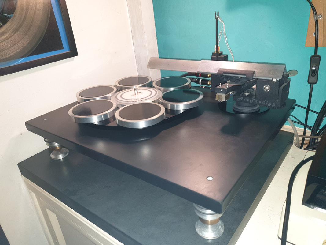
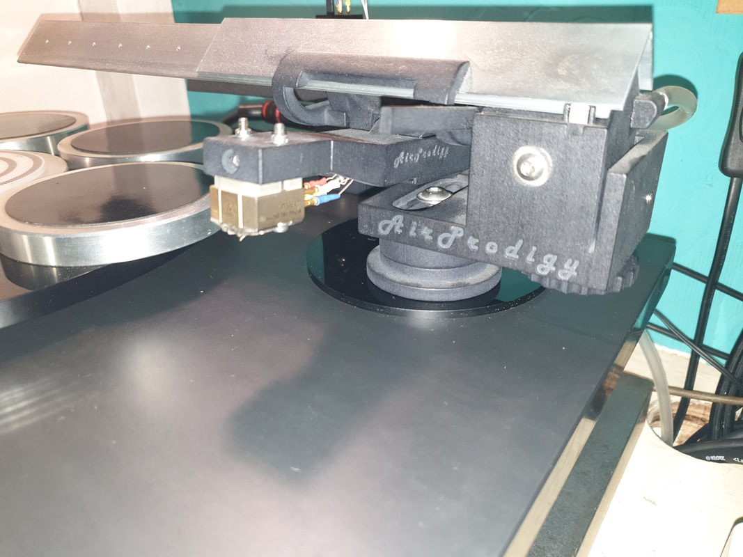
Unfortunately for everyone in the house demanding my attention, things escalated from there as I decided I wanted to try my airprodigy arm on the deck as it has been sat unused for about 12 months, (partly because of the dodgy old plug) and seeing it spinning for the first time in a long time set me off.
The arm board needed surgery to fit the new arm as the last arm it had on it was an at1100 I had. So I stuck it in the lathe and machined off the original perspex face, superglued a new bit of perspex on and then machined it round.
Then measured it up, drilled it for the mounting bolt and tapped a thread into the perspex. Then dragged the Lenco out and pulled the arm off it and fitted it onto the JBE.
Sounds really good.
Took me a few hours to replace the connector, sort the arm board and mount and set up the arm, and tidy up the absolute devastation I'd caused, but it was a nice job to do. Killed a few hours.
Never did finish going through all the parts boxes......
Going forward, there are some bits I would like to attend to. I might try some different legs, I may re case the psu, and I'd like to replace the sorbothane pads on the top of the platter pods with some new rubber. If I can find a die the right size to punch some new discs out.
But for now, I think I'll just enjoy it
Fast forward to 2021................
I haven't updated in a while, but I've done some bits and pieces lately.
I got abit bored today and was tidying through a load of my many boxes bits and pieces. I was chucking bits and pieces that have been in one of the boxes for god knows how long. I found a small 5 pin locking connector, which set wheels turning, so I decided to replace the awful old connector on the JBE that connects the control box to the motor.
This connector was crap in 1978 and is even more crap now
I've always had issues with it ever since I bought the deck, so it's now gone. Had to make a bracket for the new socket, and replacing the plug on the end of the flying lead was abit of a pig as the connector is abit small. Got there in the end though.
Unfortunately for everyone in the house demanding my attention, things escalated from there as I decided I wanted to try my airprodigy arm on the deck as it has been sat unused for about 12 months, (partly because of the dodgy old plug) and seeing it spinning for the first time in a long time set me off.
The arm board needed surgery to fit the new arm as the last arm it had on it was an at1100 I had. So I stuck it in the lathe and machined off the original perspex face, superglued a new bit of perspex on and then machined it round.
Then measured it up, drilled it for the mounting bolt and tapped a thread into the perspex. Then dragged the Lenco out and pulled the arm off it and fitted it onto the JBE.
Sounds really good.
Took me a few hours to replace the connector, sort the arm board and mount and set up the arm, and tidy up the absolute devastation I'd caused, but it was a nice job to do. Killed a few hours.
Never did finish going through all the parts boxes......
and the obligatory full deck shot