Goldring G99 Restorations
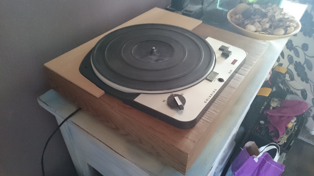
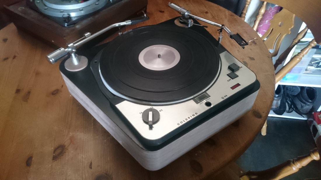
I picked up this goldring G99 from a friend who had had it in his attic for a number of years. Having a collection of decks including a garrard 301 in a slate plinth, the 99 had been relegated and was not in use. Cosmetically the deck was in fair condition with the usual knocks and lumps out of the paintwork you would expect from a deck that is now over 50 years old.
There were only a few relatively minor issues to fix before the deck was ready to be mounted in a suitable plinth.
Firstly, the neon for the strobe didn't light up. Investigating this revealed that the dropper resistor (in this case a 100k carbon comp) had fractured along the line of the metal end cap. It wasnt immediately apparent that there was a dropper at all as it was shrouded in yellow heatshink. However, it fell out when jiggling the wiring about. Duly replaced with a new one, the strobe was back in business.
Secondly, when it was initially spun up the speed selector was pointing to 16 rpm when 33 rpm was set via the strobe. A nice simple fix. The selector mechanism employs a gear on the end of the shaft that when rotated moves a corresponding crescent gear on the end of the selector linkage. As the shaft is keyed for the control knob, it meant that the shaft had to be dropped. Simple to do. First, set the speed to 33 via the strobe, ignoring the knob postition. Second, remove the retaining c clip with long nose pliers, third, push the shaft down so it disengages from the crescent gear and rotate it so that it lines up, then pull it back up and refit the c clip and control knob.
The bearing and motor were both serviced, both were given a complete strip, assessment, clean, relube and rebuild. The bearing was treated to a ceramic ball in place of the worn standard hardened steel one along with its rebuild. It is now rotating beautifully smoothly and silently. neither will need touching for years to come. In the meantime, I had also building the plinth :-)
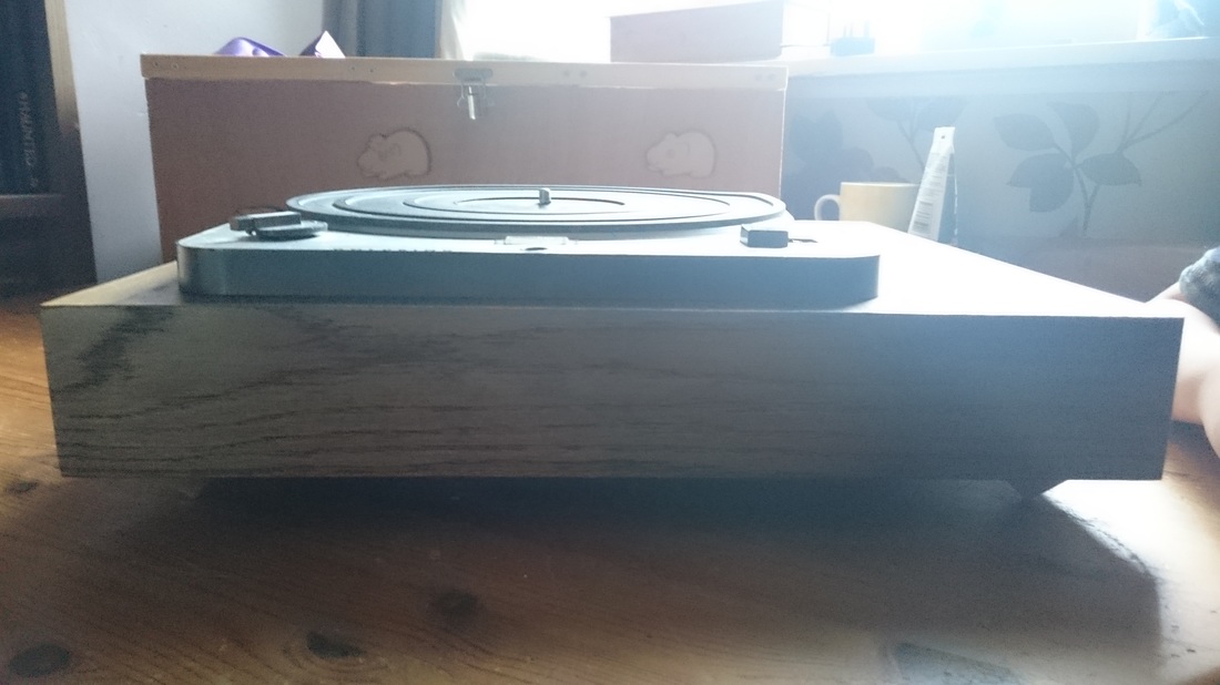
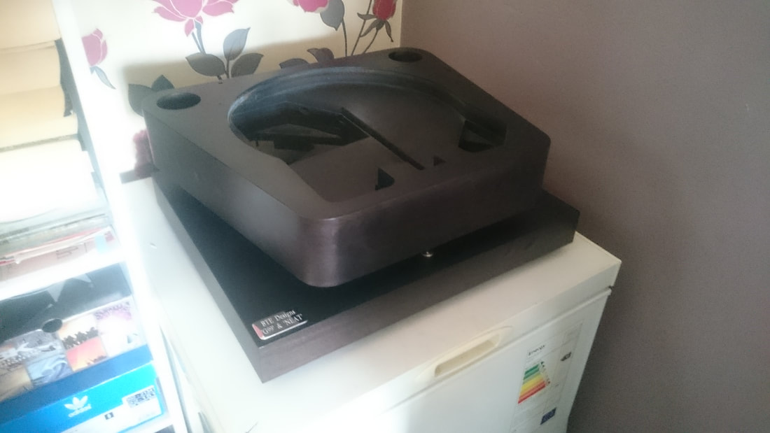
So. What to go for in terms of the plinth. Well it was a no brainer to build a solid cld plinth in the style I usually do, with alternating layers of ply and mdf. A box type plinth was a no no as that would just be a recipe for rumble.
So i set to it and built the plinth in this manner and veneered with oak. The oak was then treated to a Jacobean dark oak danish oil as i wanted to darken the plinth down some.
The interior of the plinth cutout and the underside was sprayed matt black before veneering as its these little details that make all the difference to the overall quality.
However, when i had finished and dropped the deck in place, it looked too much. A great big slab of dark wood, and not exactly what I was looking for. I had made and sprayed a silver arm board but it looked abit lost in the swathe of oak. I wanted to capture the look of those high end Japanese direct drive decks from the 70's that had beautifully veneered plinths combined with the silver of the drive mechanisms such as the JVC QL-Y5F and QL-70 or the Denon DP ranges.
I wanted the plinth to fit with the look of the motor unit and not look like a plinth with a deck in it, rather the deck take centre stage and the plinth a step back in the overall look of it.
And to slim it down a little as it is a big bugger at 18" wide by 15" deep by 4" tall including the cone feet I turned on the lathe for it.
And retain the clean look of the plinth without adding any frilly pointless lines.
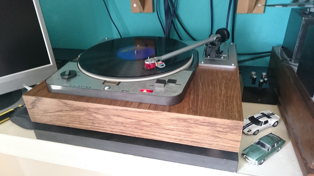
So after abit of thought and several sketches I decided on a full length trim panel that used the lines of the deck for its shape.
The deck actually has 7 sides,so i used the kink in the left and right hand sides as a datum to size the trim panel in the front to back dimension as i felt that using the lines of the motor unit would produce the clean look to the trim I wanted.
I decided to use pan head screws to attach it rather than glue as alot of the Jap decks i took some inspiration from had semi decorative hardware on them, and being a pedant and abit of a perfectionist, agonised for over an hour over the placement of the rear central screw. Yes I know, that does take the piss abit, the missus when asked several times if it looked better in one position or the other told me to "piss off and stop being so bloody pedantic", and there would only ever be me who cared about the position of a 'bloody screw'.....................
here it is roughly cut
So i set to it and built the plinth in this manner and veneered with oak. The oak was then treated to a Jacobean dark oak danish oil as i wanted to darken the plinth down some.
The interior of the plinth cutout and the underside was sprayed matt black before veneering as its these little details that make all the difference to the overall quality.
However, when i had finished and dropped the deck in place, it looked too much. A great big slab of dark wood, and not exactly what I was looking for. I had made and sprayed a silver arm board but it looked abit lost in the swathe of oak. I wanted to capture the look of those high end Japanese direct drive decks from the 70's that had beautifully veneered plinths combined with the silver of the drive mechanisms such as the JVC QL-Y5F and QL-70 or the Denon DP ranges.
I wanted the plinth to fit with the look of the motor unit and not look like a plinth with a deck in it, rather the deck take centre stage and the plinth a step back in the overall look of it.
And to slim it down a little as it is a big bugger at 18" wide by 15" deep by 4" tall including the cone feet I turned on the lathe for it.
And retain the clean look of the plinth without adding any frilly pointless lines.
So after abit of thought and several sketches I decided on a full length trim panel that used the lines of the deck for its shape.
The deck actually has 7 sides,so i used the kink in the left and right hand sides as a datum to size the trim panel in the front to back dimension as i felt that using the lines of the motor unit would produce the clean look to the trim I wanted.
I decided to use pan head screws to attach it rather than glue as alot of the Jap decks i took some inspiration from had semi decorative hardware on them, and being a pedant and abit of a perfectionist, agonised for over an hour over the placement of the rear central screw. Yes I know, that does take the piss abit, the missus when asked several times if it looked better in one position or the other told me to "piss off and stop being so bloody pedantic", and there would only ever be me who cared about the position of a 'bloody screw'.....................
here it is roughly cut
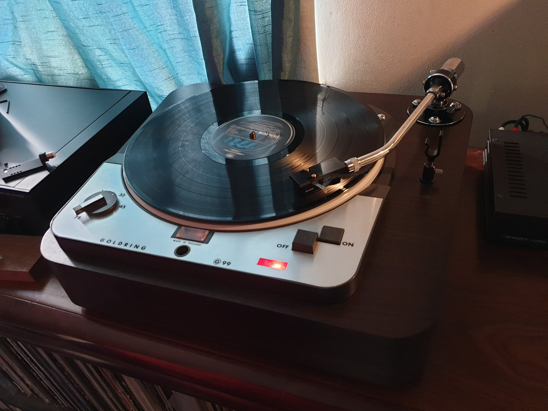
and with a quick silver blow over to check the look after cutting the arm rebate
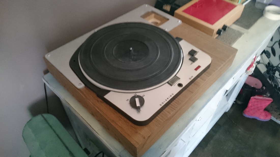
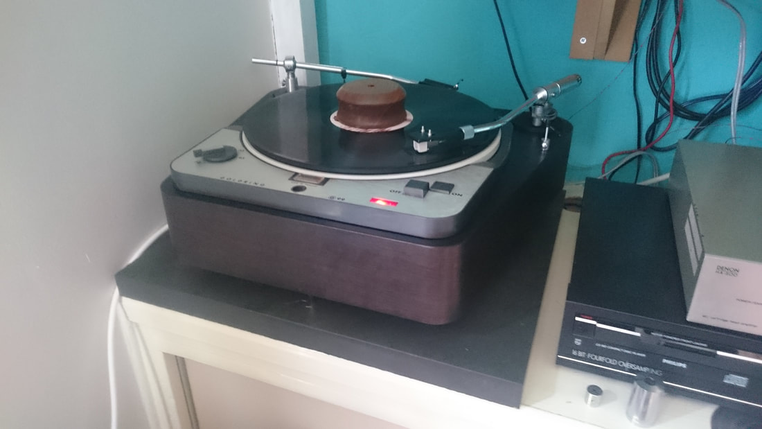
Happy with the overall look, I then made an arm board to fit the modified origin live arm and a spare blank one to accommodate one of my other arms at a later date.
I added an IEC socket on a silver plate to the rear and added a chassis ground wire to the underside of the motor unit for safety, using a ring terminal and one of the preexisting mounting screws for the deck fascia panel.
Then booted the JBE out of the way, set up the arm and had a listen to abit of Swing Out Sister
Wonderful! :-)
The sound quality was never in any doubt, it did exactly what I expected, and sounds fantastic. With the guts that idler drive decks are famed for at the bass end, with great tightness and speed, a midrange to equal anything you would care to put it up against, and treble that i find to be a fair bit better than contemporary alternatives such as the 301 and 401. I think these motor units are well up there on an equal footing with the 301 and 401 and very underrated.
The caveat as ever is that the plinth for this type of motor unit, whether it is one of these, a l75 lenco, a 301, 401, TD 124 ,Connie, etcetera, really needs to be carefully looked at.
If you don't want rumble, want tight bass, want a glorious midrange and treble, and want to get the best from something like this, you need mass and effective damping and energy transfer.
Get it wrong, and you will soon understand why these sort of decks died out to be replaced in the mainstream by belt drive decks such as the lp12, Roksan xerxes or the Mitchell Gyrodec.
As for me, I think they have a certain something that those decks will never have........
Next up, we have the second G99.
This one was a commission rather than for me, and the brief was to have a plinth that could accommodate 2 1960s NEAT tonearms. One was a consumer version, and the other a broadcast arm. I had an idea for a compact plinth with a slight angle to the sides as there was a certain size limitation.
These arms were pretty difficult to find any pertinent data on them, there was next to nothing available. Some trial and error was required to get them both set up. The closest data for the null points and S/P distance turned out to be a Denon DA307 (iirc)
The top was painted satin black and the sides were veneered as one continuous piece.
The plinth was specced to have a levelling base, and the finish on the walnut was stained as dark as possible with ebony stain so that it was almost the same colour as the top. Once this was dry, the entire deck and levelling was was coated in a satin clearcoat so that the join between the black top and veneered sides was seamless.
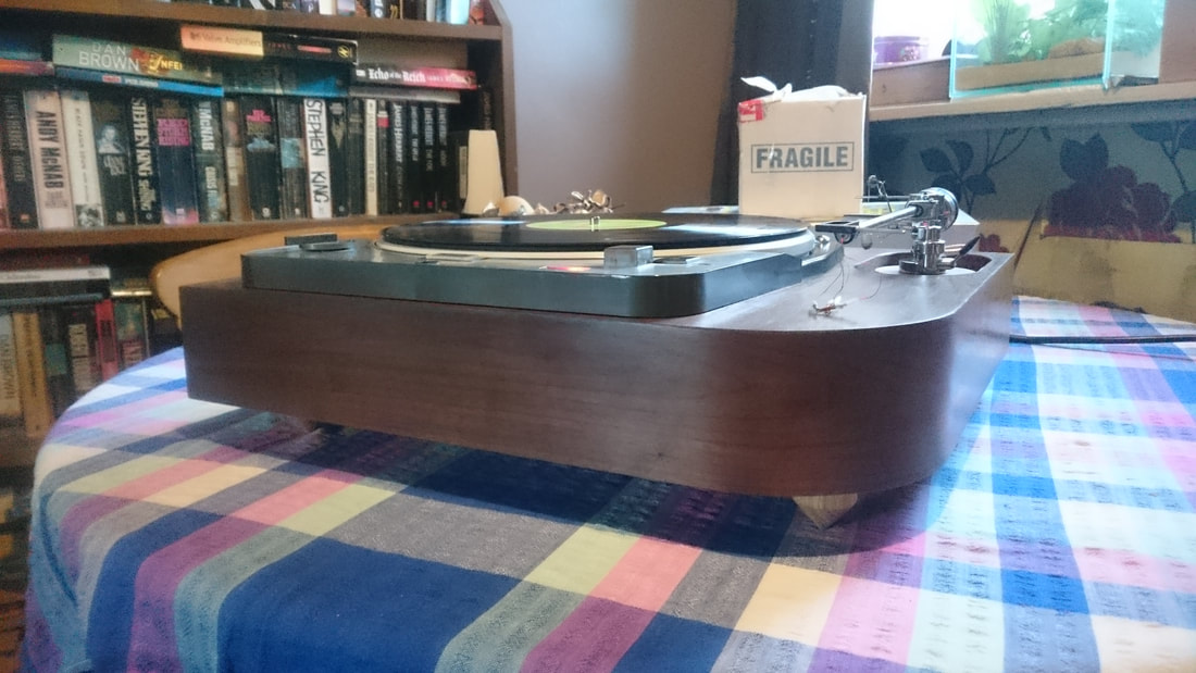
The 99 itself was stripped and rebuilt from the ground up as there were several problems. The motor was completely rebuilt as the rotor was hitting the stator windings. So it was rebuilt and the stator windings repositioned on the proper position. They had somehow moved downward over time. the bearing was rebuilt and the neon for the strobe had its dropper resistor replaced. Exactly the same fault as the first one, right down to the place where the resistor had cracked..... Here it is without the levelling base, I couldn't use it as the shelf bracket in the picture was in the way. You can see the contrast between the darkened walnut and the satin black top
The arm boards for the 2 neat arms were turned from solid walnut on my lathe and have an offset mounting hole. This is to allow the spindle to pivot distance to be varied as there was no information on what this was for the neat arms, one proved to be different from the other. In this picture the rear arm was sans counterweight as it was perilously close to the side wall and i didn't want to damage it. A different design altogether from the first G99 restoration.
The arm boards for the 2 neat arms were turned from solid walnut on my lathe and have an offset mounting hole. This is to allow the spindle to pivot distance to be varied as there was no information on what this was for the neat arms, one proved to be different from the other. In this picture the rear arm was sans counterweight as it was perilously close to the side wall and i didn't want to damage it. A different design altogether from the first G99 restoration.
And here we have the next restoration.
This one was commissioned by a friend of mine, and the brief was well.... brief. 2 things, it was to be walnut veneered, and it was to have his Hadcock gh242 fitted.
There was one complication. The 242 had been rewired and this meant that the height adjustment was compromised by the much thicker leadout wires coming from underneath the little red socket in the arm base. Basically it wouldn't go low enough for a lot of cartridges.
On his original plinth he had shimmed the 99 up by 10 mm by putting an mdf spacer between the plinth and the motor unit so it worked, but was pretty ugly. I decided to put a rebate into the plinth for it so that the install was much neater.
Now the motor unit itself was perfect, no work was needed at all, and original down to the original mat.
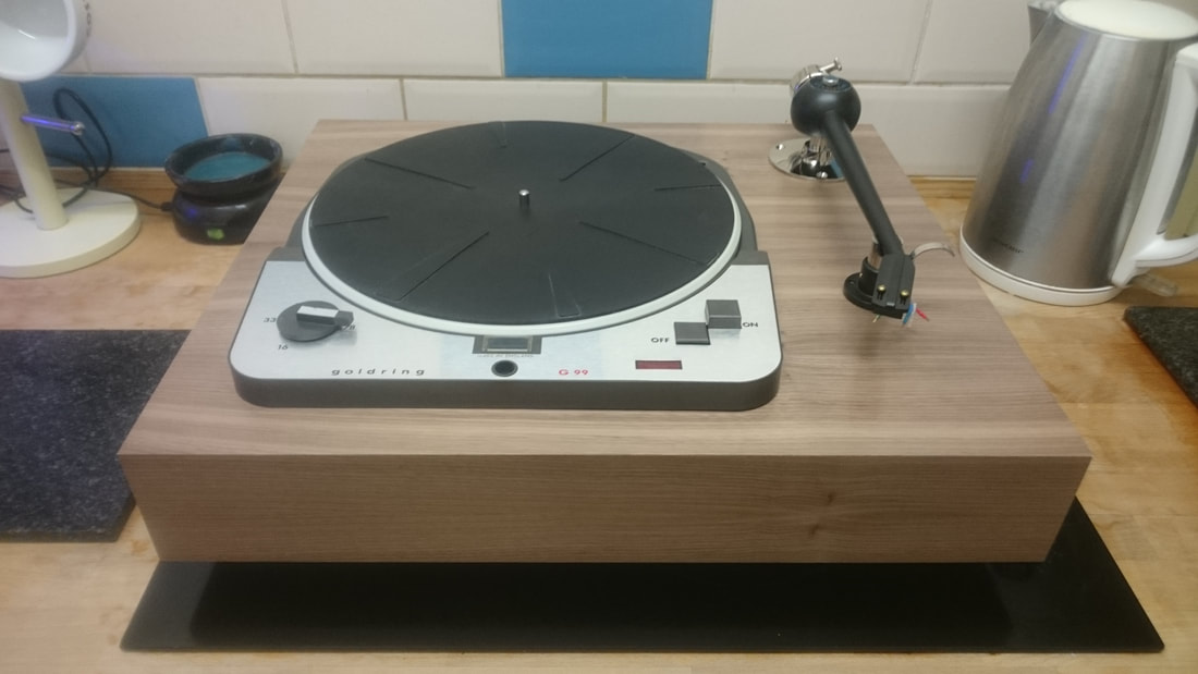
I decided to cut the front right corner off and round it, as I felt that in a similar way to the first restoration I did, that there was too much plinth. A big slab of walnut in this case. I think that the rounded corner draws the eye and cuts the profile abit, making it less in yer face. The walnut veneer had a walnut dye applied to make it more... err... walnuty, and emphasise the colour
I decided to cut the front right corner off and round it, as I felt that in a similar way to the first restoration I did, that there was too much plinth. A big slab of walnut in this case. I think that the rounded corner draws the eye and cuts the profile abit, making it less in yer face. The walnut veneer had a walnut dye applied to make it more... err... walnuty, and emphasise the colour
The feet are oak cones, and the arm board is made the same way as the 2 arm 99 ones were. I turned solid walnut again and offset the mounting hole so that there is now a degree of adjustment for the hadcock. I felt this was important as the hadcock has fixed mounting holes for the cartridge and not all carts work with the same overhang measurements. The adjustment works in essentially the same way as an SME arm base does, by allowing the spindle to pivot distance to be altered instead of the cartridge position.
My friend has used both his Denon DL103D and his audio technica AT33 moving coils in the arm
Next up we have the most recent G99 build. This one posed one or 2 issues to deal with.
My friend has used both his Denon DL103D and his audio technica AT33 moving coils in the arm
Next up we have the most recent G99 build. This one posed one or 2 issues to deal with.
When I got the 99 from my client it had not been run in years, and had an issue with the strobe window. The plastic reflector underneath the window had lost all its mirror coating so would need sorting. I tried chrome paint and a piece of polished stainless in the bottom of it but they weren't clear enough to see the speed markings as well as I wanted. In the end I cut a piece of mirror glass and fitted it into the reflector. That sorted it.
In the meantime my client had decided on a Karmadon 12" arm to go on the deck. I'd held off starting the plinth until the decision was made so that the plinth could be sized appropriately. He also supplied a Dynavector DV20x2 high output moving coil cart to be fitted to the deck.
The plinth was built so that the arm and the deck had a 1 1/4" distance from them to the edge of the plinth so that it all looks in proportion, i.e the plinth looks the right size and not too big or small. I then veneered it in walnut with no stain and a coat of clear finishing wax. I wanted the plinth not to look massive so chose to go lighter than usual with the finish to contrast with the dark grey of the deck and the black of the arm. It's actually 22" wide by 18" deep so it is bloody huge in comparison with the other builds, but the lighter veneer hides the bulk pretty well
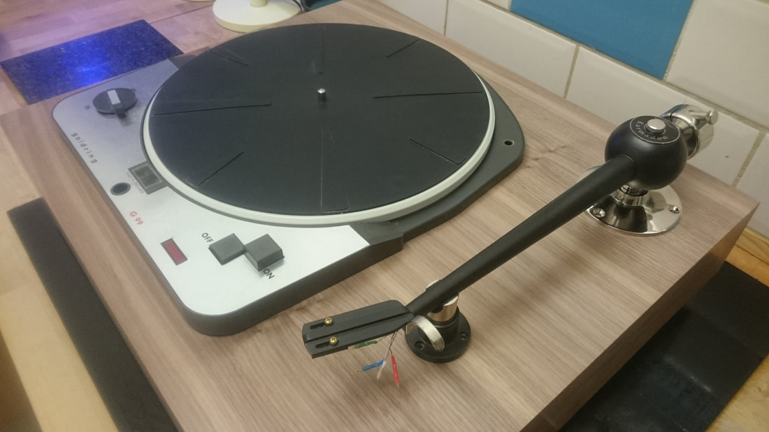
The Karmadon arm is a lovely piece of work. It requires a terminal plate making as it is supplied with a bare wire termination. So a socket plate was made up to go on the rear of the deck along with an earth post to attach a separate earth wire to. It looks pretty massive and looks as if it should have a high moving mass. In reality its not as high mass as it looks. All the weight is around the pivot, the ball shaped bearing housing and the heavy counterweight are the heavy bits and they are concentrated around the pivot where they don't affect the effective mass as much.
When I first got my hands on it I was abit dubious about putting the dynavector in it as I thought it would be too heavy, and was more geared towards carts like the dl103. However once I took the shim off the headshell and realised how heavy the shim was, I realised that the arm is alot more versatile than it first appears.
With the Dynavector in it, it positively sings. I would heartily recommend this arm if you can live without bias.
The next problem was testing it. It was too big to put it where my other decks usually go, so I had to borrow an Ikea lack table to put it on. And string cables all over the place to get it connected up.
The next snag was hit when it was run. Pitch was not stable. By this time I had rebuilt the motor and bearing, and it has a really quiet motor indeed. So it had to be the idler wheel as there was nothing else to look at.
When I had a close look at the idler wheel which was the original plastic one, it looked to be the tyre that was abit hard on the drive edge so it was losing traction. I went to dress it back a little in the lathe, and noticed that the bearing bush wasn't actually in the centre of the wheel! It wasn't out by a teeny bit, it was out by a lot. So it got binned and an Audiosilente CNC machined idler wheel was fitted.
I also used degreaser on the platter drive surface and motor spindle to make absolutely sure there was nothing to cause any issues. No more pitch wobble.
The combination of the 99, Karmadon and Dynavector is very nice indeed, and I was very sorry to see it go. I must have another Dynavector now..................
Onto the most recent restoration
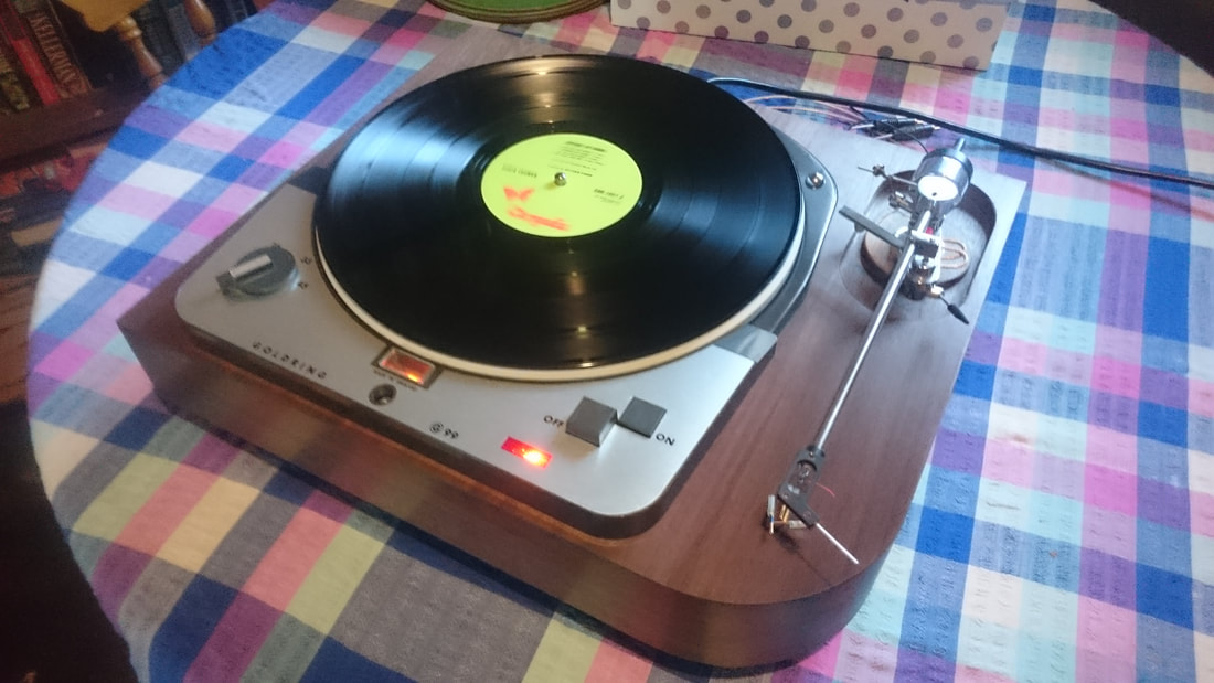
This deck was built for a gentleman over in Ireland, and came to me before he had even seen the deck!
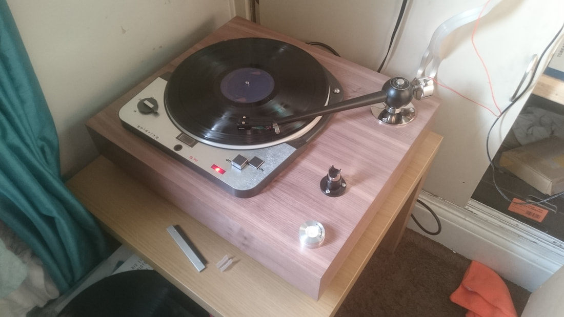
It was bought from another gentleman who I know through a forum so I knew it was a good one. It didn't require anything doing to it, but I rebuilt the motor and bearing and gave it a thorough checkover, and put in new wiring as the original looked abit tatty and a little short. Perfectly functional, and in servicable condition, but not quite long enough to get to where i wanted the IEC socket to sit.
The plinth is an extended version of plinth number 2 I did, see above, so that the arm which is an Audio Technica ATp12t would fit. The cartridge on it for testing is a Dynavector DV20 x2h.
Told you I'd get one ;-)
It was fitted with a Denon DL103 when it got to its destination
It required absolutely bomb proof packaging to get it over to Ireland, which cost a bomb too (UPS) but it was worth it for the peace of mind that unless the UPS van went off a cliff that it would get there in the intended number of pieces.
Other than having to recess the base of the arm into the plinth to get the required height adjustment, this one was a pretty straightforward build. No particular snags other than the fact that I made a pigs ear of the original finishing of the veneer so I had to take it all off and start again.
Onwards!
